4000 series CMOS 24 hour clock

 For the last couple months a friend and I have been working on a 4000 series based clock in electronics class. After having failed building a FM receiver, we opted for a clock. We didn't go the microcontroller way, but old school ICs. So, we created a circuit for a simple clock. I opted for a 24-hour version, while my friend made the 12-hour equivalent. 

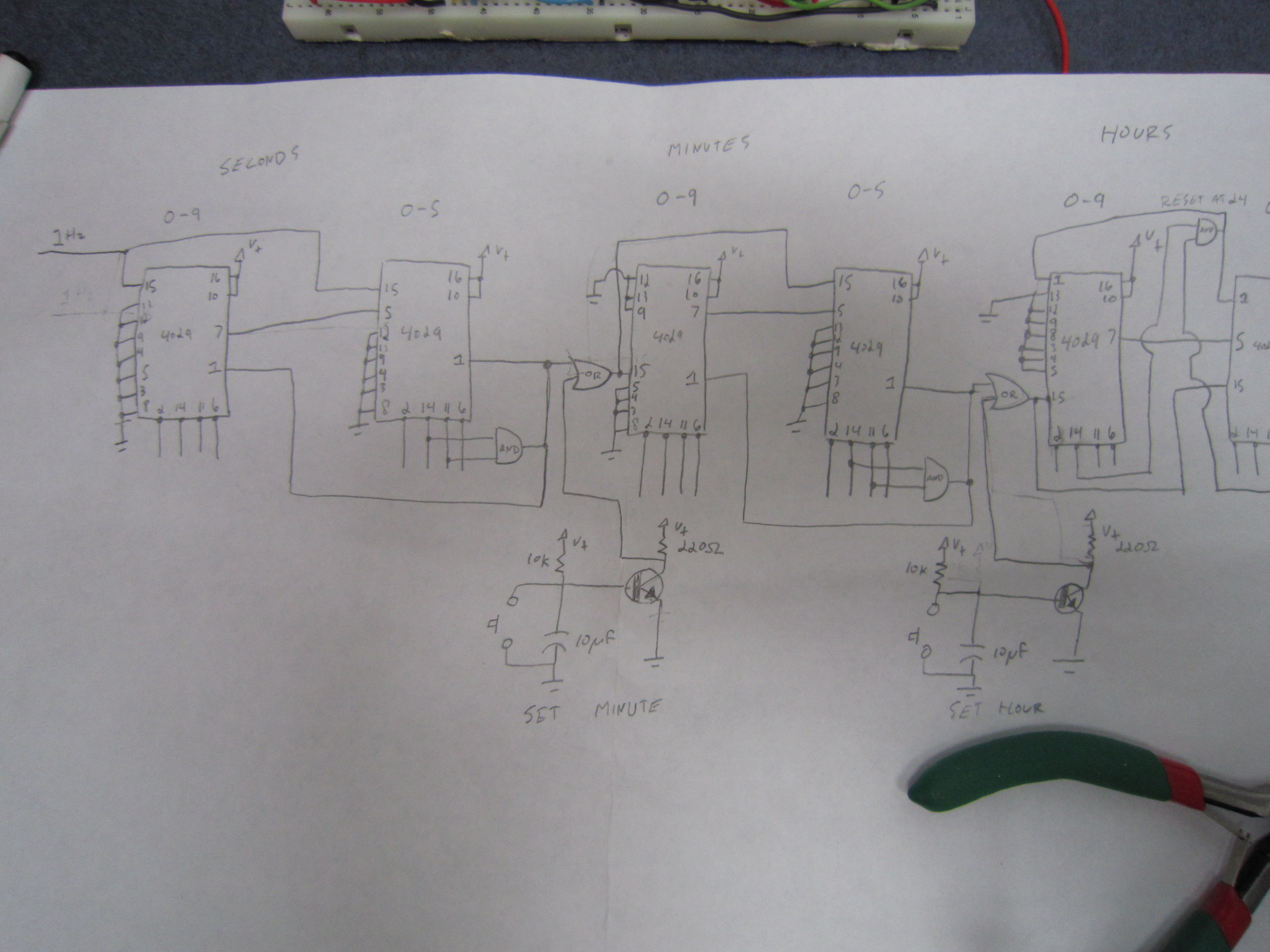
The above image was the basis of the circuit. Not shown was a 4060 and 4013 IC to make a nice 1Hz signal which we can use for the seconds. The rest is fairly simple: allow the seconds and minutes to count to 59 and use AND gates to reset at 60. Also pictured is the buttons to set the time. We used two 2N2222 transitors to make a NOT gate. Though, this ended up being too glitchy so I opted for a 4011 to create stable square wave.

And here's the clock. Incredibly disorganized but it works.

A couple months learning and work and we finally have it working! We used a 7805 voltage regulator for the entire circuit since I didn't want to add resistors to the displays. 9 volts would be much better though. 

I started using EagleCAD for the schematic but I messed up. I was adding lines instead of nets. So, my friend found DesignSpark and we used that. As far as free goes, the program is pretty easy to get going. One pain in the ass was that DesignSpark didn't have the right 7 segment display. We ended up creating them from scratch, see the attachments to download it. 

I didn't have enough time to create a PCB out of it which is disappointing. Although, my friend ended up making his, albeit with his schematic rather than mine, the PCB turned out to be a bit larger than an A4 sheet of paper. Not small at all.

Anyway, it was a fun project to make and I definitely learned quite a bit along the way. 

See the attachments at the bottom to download the schematic as a PDF or the DesignSpark project.

Edit: Note that the 1N4004 diodes should be 1N4148 instead. DesignSpark does not have these diodes in the libaries.