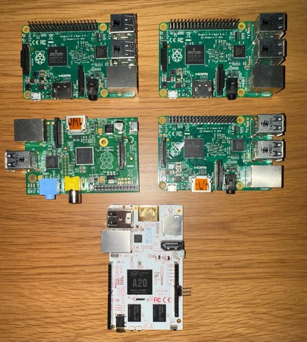
I “accidentally” won an eBay auction for five single board computers, four of which are Raspbery pi’s. By accidentally k mean I bid on an auction and didn’t expect to win. Lo and behold, colour me surprised when I get a notification I now had to pay for my order.
I’ve had a Raspberry Pi Model B+ (2011) since approximately they launched in 2012. Until very recently, it was an RTL SDR and AdGuard home server. Both of which have performed well on a 900Mhz/512MB RAM system. One peripheral I have enjoyed is the component video out. While not common on modern TVs and monitors, having the option for backwards compatibility opens up the possibility for reviving old electronics.
Of the single board computers I purchased, three were Raspbery Pi 2s rev 1.2, one Raspberry Pi B+ and one pcDuino 3 Nano. I’ve run DietPi with great success on these ARMv6/7 boards and continue to do so. I can simply dd the disk image to an SD card, edit the dietpi-config.txt file on the FAT partition, boot up, have DHCP configure networking and SSH in.
The TV
Analog TV broadcasting ended in Canada in 2011 when signals were switched to digital. This meant the classic bunny ear antennas no longer worked unless you purchased a digital set top box to convert the digital signals. Having nothing but time on my hands, I purchased one such box and a yagi antenna in the hopes of receiving any digital signals. The thing with analog is even if the signal is weak, you could still tune to the channel and receive a fuzzy picture. Not quite so with digital.
Living rurally, I had zero hope of receiving anything to be honest. FM radio I can receive clear as bell. Digital TV Transmitting stations are well over 60km away, nevermind mountains and trees in the way. Using a few sites to determine the angle to direct the antenna, I had zero luck.

It’s quite refreshing to find websites that, seemingly have not updated their design from the mid 2000s, are dedicated to OTA TV signal finding. Granted my antenna is only 20ft off the ground on an elevated hill (I guess all hills are elevated...), jumping into SDR++ to see what’s out there also confirmed my absence of reception.
So with OTA TV out the window, my next project was to build a makeshift TV box with the Raspberry Pi b+. My goal is to simply turn on this 5” RCA TV and have a TV program appear.

In the past, I’ve used other video consoles on this TV by using a VCR as an RF modulator and tuning to channel 3. With no VCR on hand, Aliexpress was my next step to find a cheap component to RF modulator.
I was able to find one for under $10 CAD, and (im)patiently waited.

In the mean time, I was able to work on the software part of this project. Coincidentally, I have an AV out to RF GameCube adapter.


The pinout is quite simple. Using the +5v and GND from the GPIO pins, the Raspberry Pi’s component out corresponds to Pin 9

on the GameCube adapter.
Conceptually in the mean time I was able to test the build while the Aliexpress order was in delivery.

The time came, I drove to the post office and picked up my 15 separate Aliexpress packages. Unknown to me, this RF modulator had a DK/I/BG switch. I figured audio would work, so I didn’t bother with it until I had a reliable video player that could use hardware decoding working on the raspberry pi. Using a 3.5mm to component cable, I received….no audio on my TV when playing a video. Sound drivers? Nope. ALSA not installed? All good here. After some Googling, it seems that this modulator is made for…PAL TV sets. The DK/I/BG switch sets the audio carrier, which do not work with NTSC TV sets. The lowest setting at DK is still 500Khz higher than it needs to be for my TV to receive audio. So while I could receive video on channel 4, I had to tune to a higher channel to receive audio….but lose video.
Fixing The Audio
How could I transmit audio at the right frequency? Taking the little box apart left with me with no easily tunable components, nevermind the surface mount ICs beared no identifiers. I could trace the audio input back, determine the resistors and capacitors responsible for changing the audio carrier and calculate the right combination to modify, but if I could simply transmit the audio by bypassing this box then I could get audio.
I found pi_fm_rds (and pifm) and figured, great—this lets me transmit audio over FM. Pair that with omxplayer for video, and I’ve got my own little TV broadcast setup. Using a DuPont connector cut in half as an antenna, I could use the narrow band FM program to output a tone on 71.75Mhz and hear it on channel 4! Amazing.
Now to receive audio and video, I couldn’t necessarily broadcast audio over the air and use the component to RF box connected via coaxial to receive both. So I just turned the RF modulator box into an…antenna.
At first, it seemed like everything worked. Video played, audio transmitted, and life was good. But then I noticed something was off. The audio was lagging behind the video, and sometimes the pitch was wrong.
Alright, maybe it was a sample rate issue? Nope.
Maybe some weird encoding problem? Still nope.
Eventually, I realized the Raspberry Pi’s PWM clock was getting messed with, and not in a way I could easily predict.
The Clock Problem
The Pi’s PWM clock is used for audio transmission in pifm, and I noticed that running it changed the PWM clock speed from 100MHz to 250MHz. Weird, but fine.
The real problem is that it never reset back after stopping pifm, meaning the next time I ran it, the timing was completely off.
Even weirder:
• Running pifm before omxplayer caused pitch issues.
• Running omxplayer before pifm caused audio lag.
• Manually resetting the clock sometimes worked, sometimes didn’t.
• Rebooting the Pi was the only reliable way to fix it.
So at this point, I had two options:
1. Reboot the Pi every time. (Annoying.)
2. Actually figure out what the hell was happening.
The Fix: A Quick Clock Monitor Script
Since I didn’t feel like rebooting every five minutes, I wrote a quick clock monitoring script to log what was happening:
#!/bin/bash
LOGFILE="clock_monitor.log"
echo "Monitoring clock speeds every 3 seconds. Logging to $LOGFILE"
echo "Timestamp | ARM (MHz) | Core (MHz) | V3D (MHz) | PWM (MHz)" > "$LOGFILE"
while true; do
   TIMESTAMP=$(date +"%Y-%m-%d %H:%M:%S")
   ARM_FREQ=$(vcgencmd measure_clock arm | awk -F= '{print $2/1000000}')
   CORE_FREQ=$(vcgencmd measure_clock core | awk -F= '{print $2/1000000}')
   V3D_FREQ=$(vcgencmd measure_clock v3d | awk -F= '{print $2/1000000}')
   PWM_FREQ=$(vcgencmd measure_clock pwm | awk -F= '{print $2/1000000}')
   LOG_ENTRY="$TIMESTAMP | ARM: ${ARM_FREQ} MHz | Core: ${CORE_FREQ} MHz | V3D: ${V3D_FREQ} MHz | PWM: ${PWM_FREQ} MHz"
   echo "$LOG_ENTRY"
   echo "$LOG_ENTRY" >> "$LOGFILE"
   sleep 3
done
This little script logged the clock speeds every 3 seconds, letting me see exactly what happened when I ran pifm, omxplayer, or tried resetting things manually.
Findings:
- Before running pifm, PWM was 100MHz.
- Running pifm immediately bumped it to 250MHz.
- Stopping pifm didn’t reset it back.
- Running omxplayer first caused audio sync issues.
- Resetting PWM manually worked… sometimes.
- A full reboot always fixed it.
At least now I knew it wasn’t an encoding problem. It was a hardware clock issue.
The Fix (sorta)
Once I knew the clock was the problem, I needed an actual solution:
- Manually resetting PWM via devmem2 (worked sometimes, but still unreliable).
- Forcing pifm to always use 250MHz (helped, but still had sync issues).
- Switching to pifmrds from rpitx-ui (finally stable).
- Oh yeah, using mono audio instead of stereo.
After moving to pifmrds (from Rpitx), the clock sync issues were completely gone. It handled everything internally, and I didn’t have to fight the hardware anymore.
Syncing Audio to Video
Running omxplayer with a video wasn't instantaneous, and the time from when I ran the command to when a video would actually play in X11 wasn't consistent. I could split a MP4, extract the audio, have pifmrds play the audio portion, and then start the video but the pifmrds would run much faster and audio would be out of sync.
I narrowed it down to a 1.3 second sleep before starting pifmrds and it worked well for the most part!
#!/bin/bash
set -e
if [ "$#" -lt 1 ]; then
  echo "Usage: $0 <video_file> [FM_freq]"
  exit 1
fi
VIDEO_FILE="$1"
FM_FREQ="${2:-71.75}"
AUDIO_FILE="/tmp/$(basename "${VIDEO_FILE%.*}").wav"
# Pre-extract the audio stream if it doesn't exist already
if [ ! -f "$AUDIO_FILE" ]; then
  echo "Extracting audio to $AUDIO_FILE..."
  ffmpeg -i "$VIDEO_FILE" -vn -acodec pcm_s16le -ar 22050 -ac 1 "$AUDIO_FILE"
fi
# Start video playback concurrently
echo "Starting omxplayer playback..."
omxplayer -n -1 --loop --display=2 "$VIDEO_FILE" &
OMX_PID=$!
sleep 1.3
# Start pifmrds using the pre-extracted audio
echo "Starting FM transmission on $FM_FREQ MHz..."
sudo ~/rpitx-ui/pifmrds -freq "$FM_FREQ" -audio  "$AUDIO_FILE" &
PIFMRDS_PID=$!
cleanup() {
  kill $PIFMRDS_PID $OMX_PID 2>/dev/null
  stty sane
  exit
}
trap cleanup SIGINT SIGTERM
wait
This works well enough, but was annoying to deal with. Depending on the size and quality of the video file I'm going to play, omxplayer can take longer to start. So the 1.3 second delay wasn't reliable. This project turned into a fun idea to now a pain in the ass chore that sorta defeated the entire purpose of it.
The Long Term Solution
Why not simply broadcast the video+audio signal via composite + 3.5mm jack and have the TV pick it up via bunny ears? This would allow me to place the Raspberry Pi anywhere, especially since this inexpensive wifi dongle has negligible range. I looked on eBay for video distribution systems.
A video‑distribution system is nothing more than a powered splitter that takes one baseband video (and often audio) feed, buffers it, and rebroadcasts identical, impedance‑matched copies on multiple outputs. In commercial installs you’ll see rack‑mount distribution amplifiers (DAs) for composite, component, or SDI. In hotels and campuses you’ll see RF head‑end modulators that re‑encode each source onto its own TV channel and combine them onto one coax run.
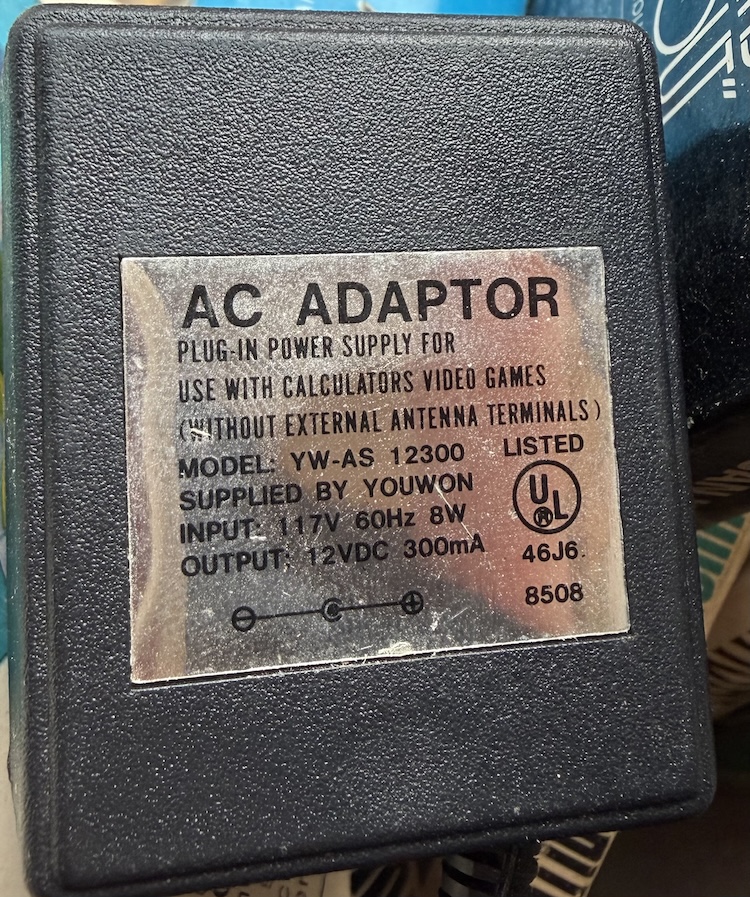
Sometimes it is crazy what people charge for old electronics on eBay, so searching through all the crap to find something that was inexpensive took some time. With the not-so-great Canadian to US dollar exchange rate, half the time the shipping cost is more than the item itself. I was able to find a TV Genie TR-200 for a reasonable sum. It's powered by a 12V brick and broadcasts on channel 14 (UHF). The real use cases of devices like these were to get a VCR or other video equipment working on old TVs that lacked a coaxial input.
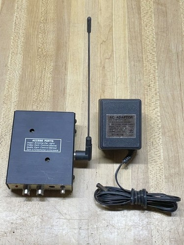
And.....it works as it should! Without messing too much with the audio and video gain, a distance of 10ft from the TV to the transmitter produces adequate video quality. Even better is it can get a bit grainy and really reproduces that TV feel.

And finally (finally!), I can do this:

| Attachment | Size |
|---|---|
| omxplayer-69c808c-bin_armv6.tar.gz | 5.99 MB |
| rpi-to-tv-01.webm | 1.53 MB |
| poster.png | 266.26 KB |
| breakfast-rp.jpg | 1.86 MB |
| monitor_clocks.sh_.txt | 743 bytes |
| start_tv_extract.sh_.txt | 844 bytes |
| boot_config.txt | 2.93 KB |
Hey, found your article…
Hey, found your article while researching to build my own PI T.V. station. I managed to find a Gemini device online like your's, but mine does not come with a power adapter. While I do have DC adapters, I could not read the polarity marking on your image of the power adapter. Is it center-positive or center-negative? Thank you!
Thanks for your comment! It…
Thanks for your comment! It's center positive, 12v 300mA. I'll add a pic of the DC adapter to this post